| |
|||
| HSG |
|
Vorbereitungen
- Vollständigkeit des Bausatzes anhand der Stückliste kontrollieren
- Bestückungsplan ausdrucken
- Grundlagen Löten
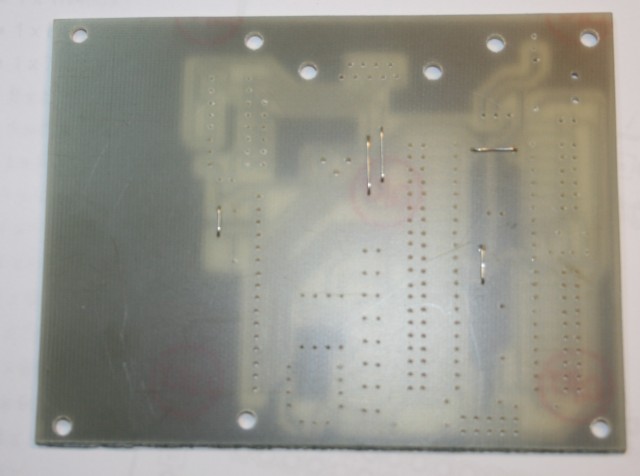
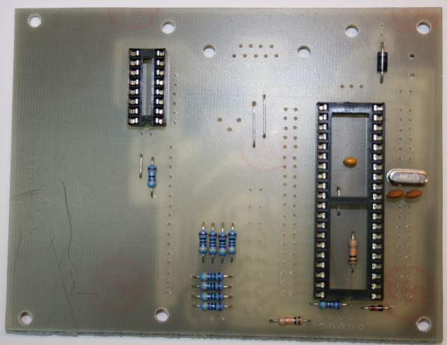
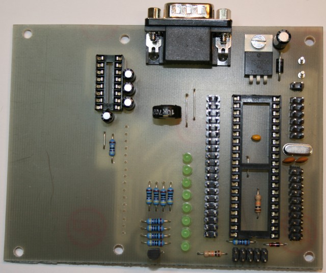
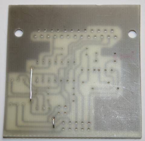
1.Schritt - Brücken
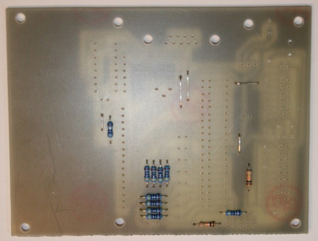
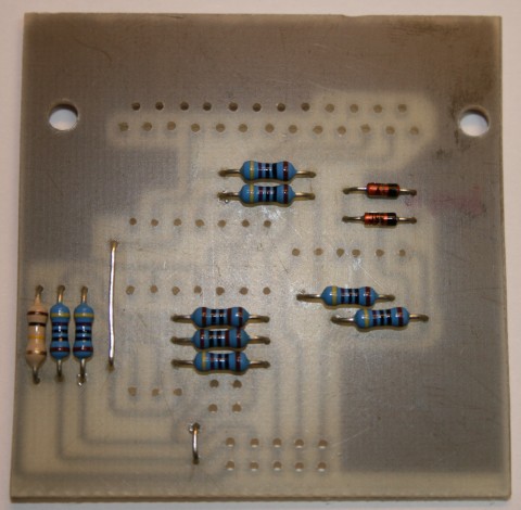
2.Schritt - Widerstände
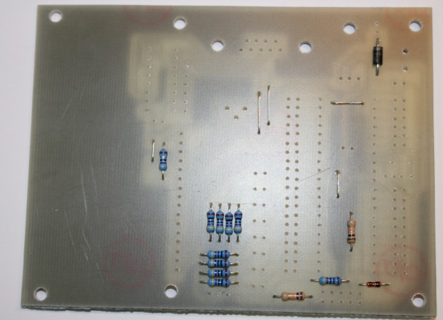
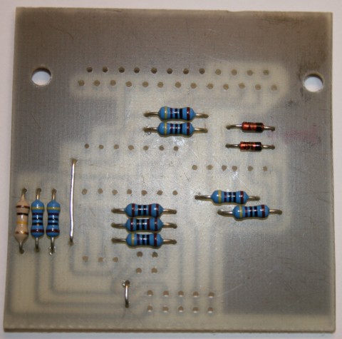
3.Schritt - Dioden
Dioden - www.elektronik-kompendium.de
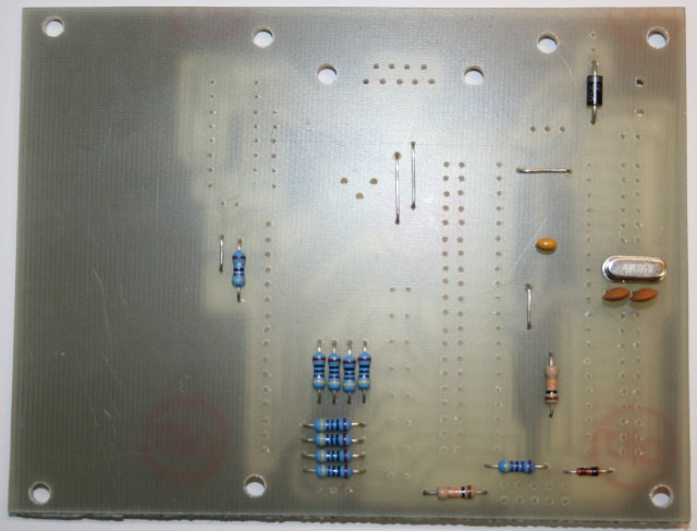
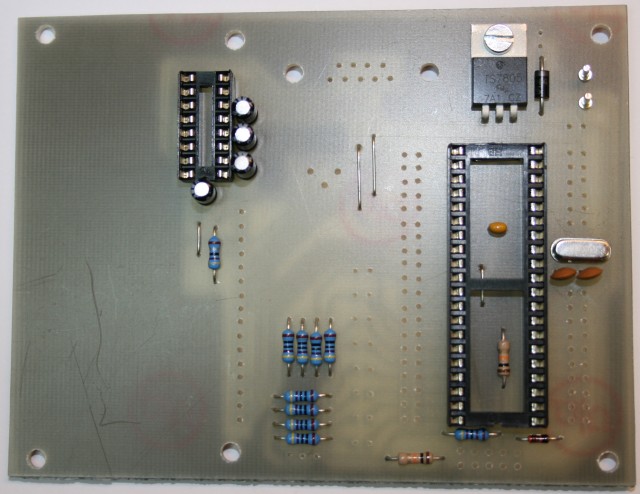
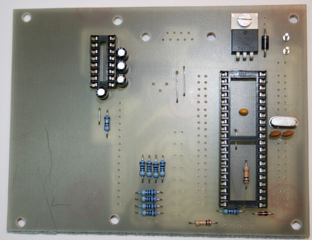
4.Schritt - Kondensatoren, Quarz
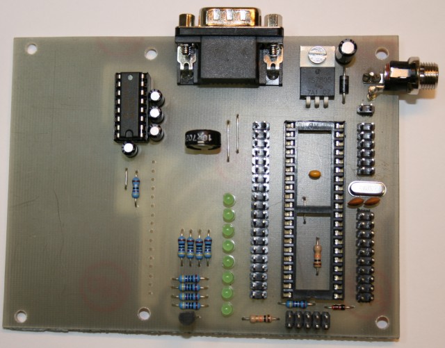
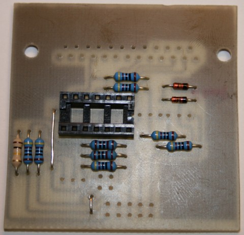
5.Schritt - IC-Fassungen
6.Schritt - Spannungsregler , Lötnägel
7.Schritt - Elekrolyt-Kondensatoren
8.Schritt - D-Sub-Buchse, Leuchtdioden , großer Elko, Potentiometer
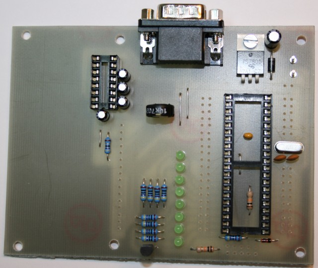
9.Schritt - Stiftleisten
10.Schritt - NV-Buchse, IC Max232
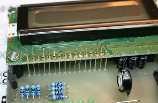
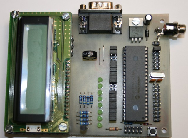
11.Schritt - LCD-Display
12.Schritt - Jumper, Reset-Taster, IC 16F877a
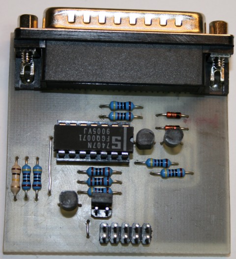
Bau des Programmierdongles
Stückliste
- 1 x Platine
- 2 x Brücke
- 1 x 25pol.-Sub-D-Stecker, Print
- 2 x 1kΩ
- 7 x 4,7kΩ
- 1 x 100kΩ
- 1 x Fassung DIL14
- 1 x 74LS07, IC
- 1 x BC556
- 2 x BC546
- 1 x ZF13, Zenerdiode
- 1 x 1N4448, Diode
- 1 x 5x2 Stiftleiste
- 1 x 2x2 Stiftleiste
- 2 x Pfostenfeldleiste 2x5
- 1 x Bandkabel 10-pol.
- 2 x Jumper
- 1 x 25pol. D-Sub-Verlängerung
![]()